Author: Kai De La Cruz
Overview
Switch-2 is a custom 12 degree of freedom quadruped continuing the Switch platform by incorporating hip roll motors in each leg.
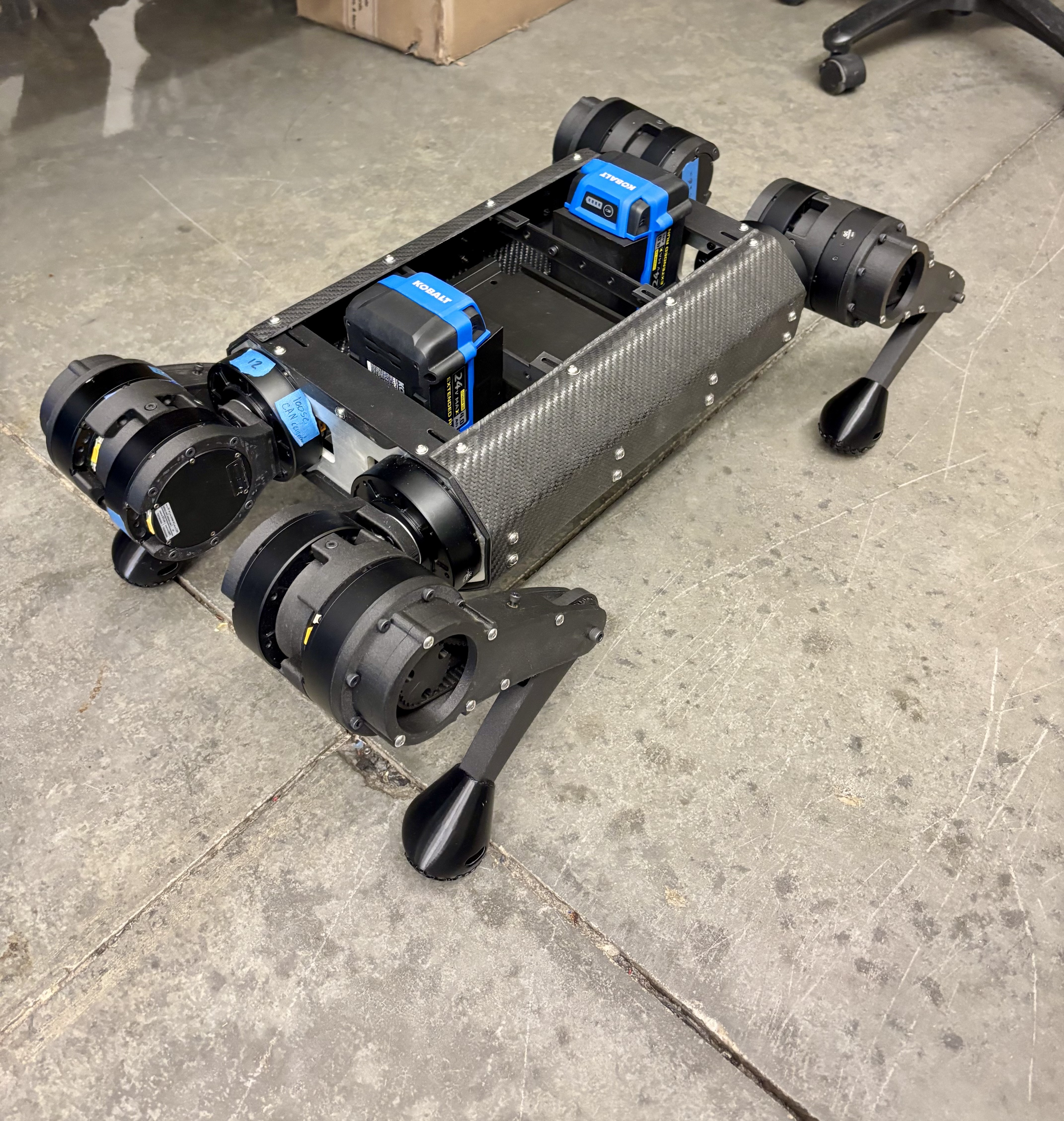
Switch-2 continues the modular design philosophy of its predecessor by providing an adaptable hardware testbed for future works. The mechanical design, manufacturing, and initial validation of this system was performed from 2024-2026 for the thesis work of Kai De La Cruz.
Objectives
- Redesign structural hardware for 12-DOF system.
- Produce more dynamically capable robot.
- Maintain modularity for future research.
Hardware
Switch-2 reuses much of the same components featured in the original Switch Hardware. The following components are either already or are intended to be implemented in the future.
GIM8108 Motor BNO08x NVIDIA AGX Jetson Orin Dev
The notable change would be the switch to Li-ion Batteries. Li-ion batteries were purchased and mounted to the chassis but are yet to be implemented with the PDB system.
Wired Communication
The wired communication for Switch-2 carries over the same set up as the original Switch with the addition of hip roll motors. This results in 2 more motors on a given CAN bus.
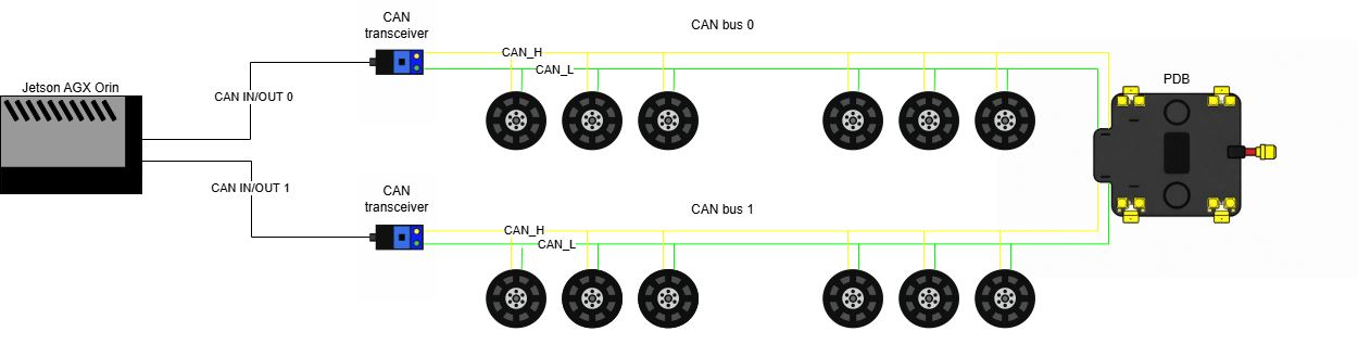
NOTE: For single-leg testing, only CAN bus 0 was used.
Software
The same development stack used in the original Switch Software section was reused. However, the default ROS middleware was used instead of Zenoh.
To connect to Switch-2, the same wireless communication protocol was used as described in Wireless Communication.
Test Nodes
To create a seamless transfer of control from sim-to-real, test nodes were developed to standardize testing procedures. This allows for control implementation to be verified in simulation prior to deploying on hardware.
A safety script is also implemented into each test to validate commands. This script rejects:
- Commands outside specified joint limits
- Trivial singularity configurations
- Commands that do not meet the Yoshikawa manipulibility measure threshold
Tutorials
Single-leg Gazebo Simulation
Startup Switch-2 Coding Environment
- Open Switch-2 Gazebo simulation project in VSCode.
- Ensure this repo is cloned to locally: SL simulation project
- Open reopen project in docker container.
- Ensure the Docker and devcontainer extensions are installed for VSCode.
- Press “Open a remote window” button in bottom left corner of VSCode, then “Reopen in Container” from menu.
- The system should be operational and ready to start
Additional Resources
Launch Gazebo Simulation
- To use ROS2, source Jazzy in one terminal by running
source startup.sh - Run
source rebuild_sim.shto launch Gazebo Ctrl + Cwill close the simulation environment.
Running Test Nodes in Simulation
Forward (FK) and inverse kinematic (IK) tests specific to this 3 DOF leg configuration
can be run by launching ROS2 nodes that handle publishing joint commands to the
joint group position controller via the command topic /joint_group_position_controller/commands.
- Launch the FK test.
source FKtest.sh - Launch the IK test.
source IKtest.sh Ctrl + Cwill end a test.
Controlling Single-leg Hardware
Remote Access the Jetson
- Power on the Jetson while close to the linked router.
- Connect remote access computer to router.
- Open NoMachine on remote access computer.
- Click on “orin” to connect to the Jetson.
- Setup system monitor and enter password if prompted.
Additional Resources Jetson Hacks NoMachine Tutorial
Startup Switch-2 Coding Environment
Prerequisites Remote access the Jetson.
- Connect to Jetson through NoMachine.
- Open Switch-2 hardware project in VSCode.
- Ensure this repo is cloned to Jetson: SL hardware project
- Open reopen project in docker container.
- Ensure the Docker and devcontainer extensions are installed for VSCode.
- Press “Open a remote window” button in bottom left corner of VSCode, then “Reopen in Container” from menu.
- The system should be operational and ready to start
Additional Resources
Startup Switch-2 ROS2 Environment
Prerequisites Startup Switch-2 coding environment (dev/Docker container) .
- To use ROS2, source Jazzy in one terminal by running
source startup.sh - In all additional terminals run
source new.sh- If you see “ros2: command not found”, this script should fix it.
Startup Hardware
- Complete Switch Pre-Startup Checklist.
- Startup CAN bus with
source enable_CAN.sh- Run this in a terminal outside of VSCode.
- The file location should be in the Jetson “Home” directory
- Connect the battery to Switch.
- CHECK AND UNDERSTAND VOLTAGE LIMITS BEFORE USE. YOU CAN BLOW UP A BATTERY.
- LiPo Batteries
- Messages on both busses should be reporting battery voltage in hex.
- Complete Switch Operation Checklist to ensure everything is working smoothly.
- Launch the real hardware controller manager to startup hardware.
source rebuild.sh- Indicator lights on motors should all turn green after running this step.
- The message “Resource Manager has been successfully initialized.” will indicate a success.
Running Zeroing
Prerequisites Started hardware
- Move robot into defined zero position and maintain zero position by hand.
- In a new terminal, launch zeroing controller.
source zerocontrol.sh- Switch-2 will immediately set zero states upon running this step.
- You should observe that the leg can now maintain its position under gravity.
- Inspect terminal for errors.
- Close zeroing controller to free up command interfaces.
source CLdeactivatezero.sh
Running Static Joint Controller
With the static controller activated, the leg is now capable of recieving position commands with specified gains.
Prerequisites Hardware zerod and zero controller deactivated
- Launch static joint controller.
source staticcontrol.sh- The leg will drive to the initial position with inital gains as specified
in
controller.yaml
- The leg will drive to the initial position with inital gains as specified
in
- To drive joints run
ros2 topic pub /static_joints_controller/commands std_msgs/msg/Float64MultiArray "{data: [0.0, 0.0, 0.0]}"where the data array contains double values of desired motor positions in radians.- Before sending a command be sure wires will not snag and that the leg is capable of desired pose.
Ctrl + Cto stop publishing position command continuously.
- At any point gains can be changed from defaults. The following set of gains
are tuned for the 3 DOF leg.
- Set Kp gains:
ros2 topic pub -1 /static_joints_controller/kp_commands std_msgs/msg/Float64MultiArray "{data: [10.0, 15.0, 50.0]}" - Set Kd gains:
ros2 topic pub -1 /static_joints_controller/kd_commands std_msgs/msg/Float64MultiArray "{data: [0.2, 0.5, 1.0]}"
- Set Kp gains:
Running Test Nodes on Hardware
Prerequisites Static joint controller must be activated
Forward (FK) and inverse kinematic (IK) tests specific to this 3 DOF leg configuration
can be run by launching ROS2 nodes that handle publishing joint commands to the
static joint controller via the command topic /static_joints_controller/commands.
- Launch the FK test.
ros2 launch rl12dof_urdf_description FKTest.launch.py - Launch the IK test.
ros2 launch rl12dof_urdf_description IKTest.launch.py
Video Tutorial