The 8-DOF MPC system was designed by Jack Butler for use on the Switch platform. The full system includes a state estimator, MPC, gait scheduler, low-level leg controller, multibody simulation, and a few smaller supporting systems. A full index of systems can be found here, and the Github repository can be found here. The system takes inspiration from the one described in MIT’s MIT Cheetah 3: Design and Control of a Robust, Dynamic Quadrupedal Robot. It’s fully implemented in ROS2/ros2_control, and written in C++.
To try out the system, clone the Git repository, build the Docker container, then run the following commands in the terminal:
source /opt/ros/jazzy/setup.bash
source install/setup.bash
ros2 launch quadruped_bringup gz.launch.py
MPC
The focus of the project is the MPC. A legged robot presents some unique control challenges - predominantly nonlinearity (the robot’s inertia depends on leg attitude, resulting in a multiplication of state variables) and changing input space dimension (each time a foot makes or breaks contact with the ground, two degrees of actuation are gained or lost). This means classical control techniques won’t cut it, so a more thorough control strategy needs to be used. The kinematic tree of the system looks like this:
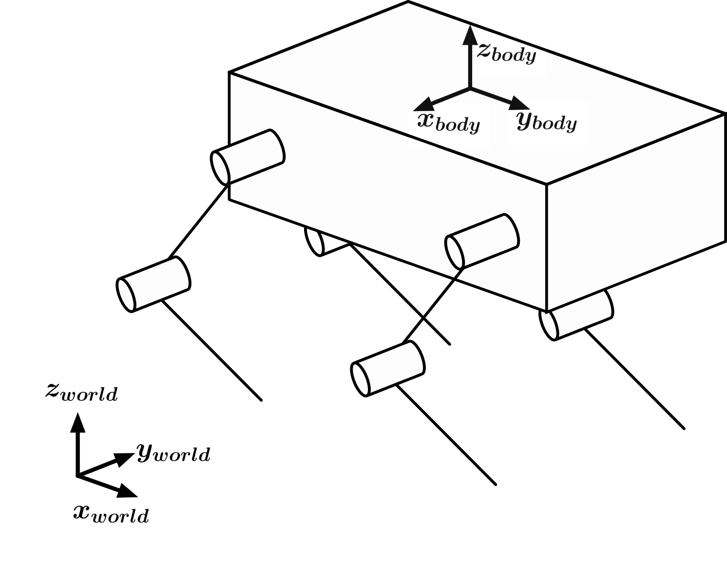
The misalignment of the body axes to the world axes are a result of the CAD produced during the BRUCE platform’s development, and isn’t relevant to what is being discussed here. The most important thing to note from the kinematic tree is the lack of hip abduction; both motors on a leg are aligned along the , meaning that it’s not possible for the system to exert a force in that direction. This is important, because it means the robot has no control over is lateral movement. This is a severe limitation.
The varying actuation of the system and its inherent nonlinearity motivated the selection of an optimal control technique. This was narrowed down to an MPC strategy by the desire for dynamic gaits, where there exist periods of non-actuation. MPC is especially well suited for this, because of its finite-time-horizon formulation. At each update, the model is simulated a few steps into the future, allowing the system to plan for these periods of non-actuation. The downside is the computational intensity; because the system is simulated many times per update, it’s too computationally costly to be run at high frequencies. The balance between model accuracy and computational weight is a key part of MPC design, and was a guiding factor in this project. The more accurate the model is, the lower the controller frequency can be before instability; the more computationally lightweight it is, the higher the controller frequency can be before overrun becomes an issue. In the end, the following model was chosen:

The MPC models the quadruped as a floating rectangular mass, actuatable by three-dimensional forces at the foot positions. Though on an 8-DOF system, the aligned forces aren’t feasible, they were modeled for compatibility with future systems. This model is used to simulate how a given set of control inputs would affect the system - an optimizer is used to push these inputs towards the desired system response. The optimizer weights are chosen to control the system’s tracking of cartesian position and velocity, rotational position and velocity, and change in controller output between timesteps (used for force smoothing). The optimizer is also constrained to prevent the optimizer from exceeding practical bounds (placing the body below the ground or higher than the legs can reach), exerting force in the direction (which can be removed for a 12-DOF system), relying on a foot in the flight state, and to allow it to anticipate future foot contact states.
State Estimation
The state estimation system is very barebones, as it was not the focus of this project. It utilizes the Pinocchio library to build a kinematic tree of the robot, which it uses to do all kinematic calculations. It estimates body velocity using some reference frame transformations and a non-slip assumption, and estimates ride height be averaging the opposite of foot heights in the body frame (). There are functions blocked out for future implementation of a Kalman filter.
Gait Pattern Generation
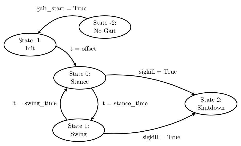
The gait pattern generator tells each foot whether it should be supporting the robot or taking a step. It does this by running the transitions of each foot’s finite state machine:
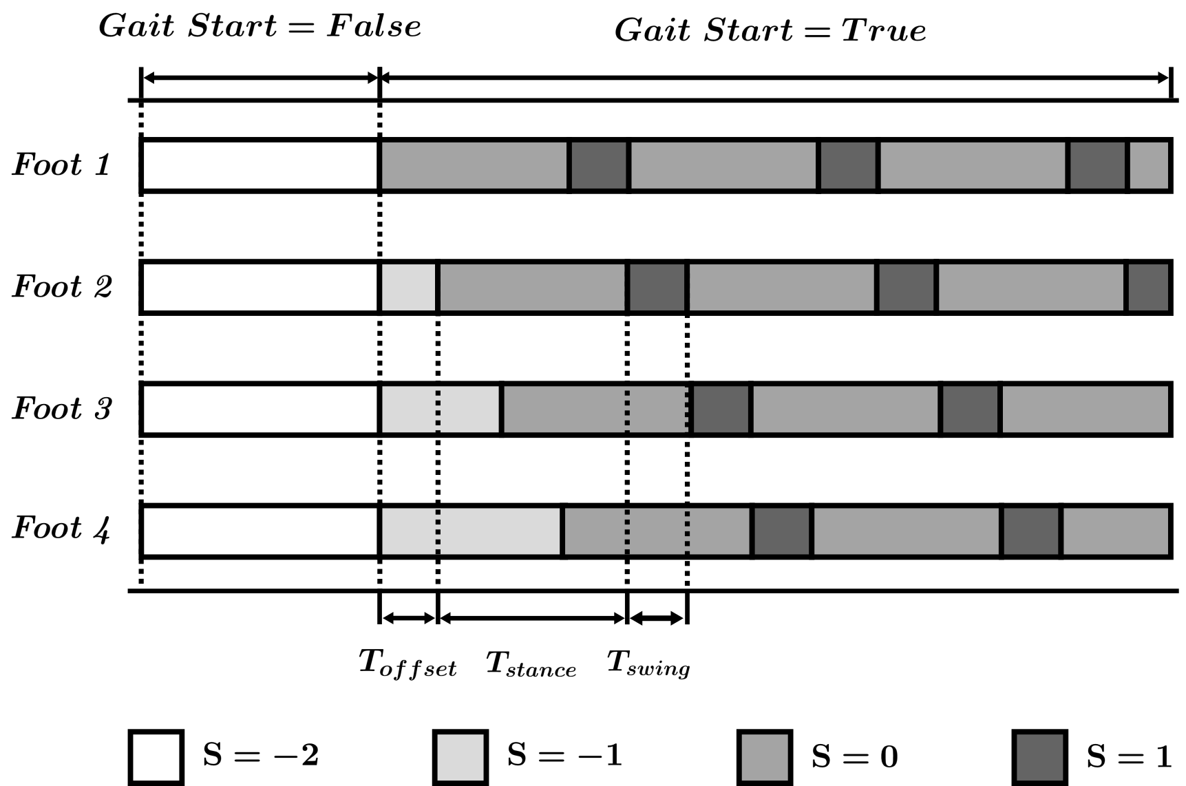
It manages the timing between these transitions, as well as the phase offset between feet - after all, a gait is just a number of feet running their FSMs with misaligned phase. The complete gait pattern looks like this:
Additionally, because of the lack of absolute position estimation, the origin must be dynamically placed. This is done using a Virtual Predictive Support Polygon (VPSP):
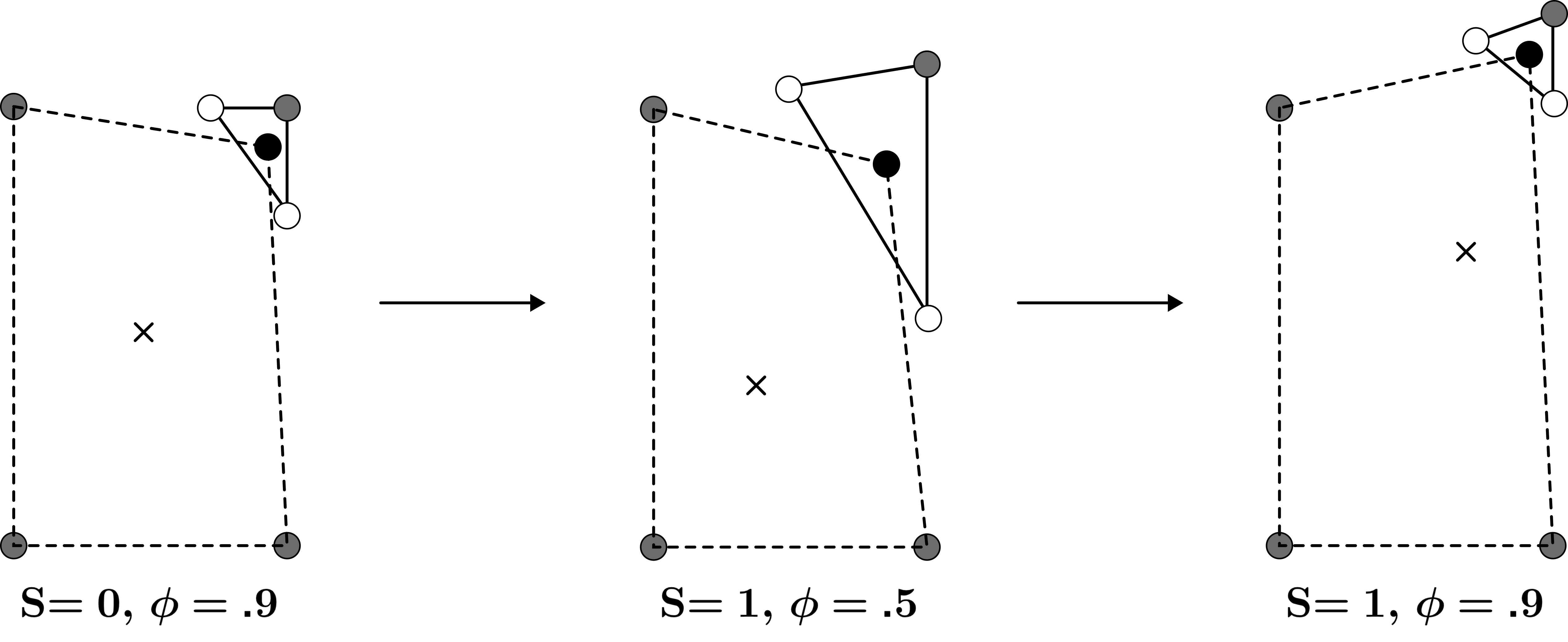
In essence, the VPSP places the origin at the centroid of the four foot positions, then biases it away from feet in flight and towards feet in stance. This allows the robot to lean towards a foot that it can “trust”, and away from one it “can’t trust”. The result is a dynamic reference frame that constantly biases the robot towards the “best” balance point. The MPC is always given a desired position of , so it’s constantly driving the body to this position.
Foot Control
The foot controller runs the nodes in the foot FSM. Recall the FSM:
The foot controller is doing the same thing during ; applying the Balance Controller’s desired forces. When the , the foot controller runs a PD position controller along a Bezier Curve generated during the transition from to . This Bezier Curve is defined with:
input this image