I2C stands for inter-integrated circuit, and is a 2-wire interface. These 2 wires are:
SDA - Serial data line SCL - Serial clock line
A typical I2C message might look like this:
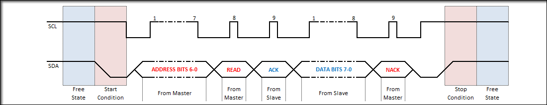 Each peripheral has a 7-bit ID that is used to signify which peripheral a message is meant to be sent to. A two-byte I2C message might look like this:
| Address Byte | b7 | b6 | b5 | b4 | b3 | b2 | b1 | b0 |
|---|---|---|---|---|---|---|---|---|
| read/write | ID bit 6 | ID bit 5 | ID bit 4 | ID bit 3 | ID bit 2 | ID bit 1 | ID bit 0 | |
| Data Byte | b7 | b6 | b5 | b4 | b3 | b2 | b1 | b0 |
| data bit 7 | data bit 6 | data bit 5 | data bit 4 | data bit 3 | data bit 2 | data bit 1 | data bit 0 | |
| Like SPI, I2C has a number of configurations that are chip-dependent, and reconfiguring the driver may be necessary before sending a message to a peripheral. The core difference between the two is that SPI is roughly 10x faster than I2C, but I2C only requires 2 pins. |
When wiring I2C, it’s important to remember pullup resistors on the line. It is standard for I2C pins on a device to be wired open-drain. Only one pullup resistor is necessary for a whole I2C line:
I2C wiring
⚠ Switch to EXCALIDRAW VIEW in the MORE OPTIONS menu of this document. ⚠ You can decompress Drawing data with the command palette: ‘Decompress current Excalidraw file’. For more info check in plugin settings under ‘Saving’
Excalidraw Data
Text Elements
Controller
SDA
SCL
Peripheral
SDA
SCL
Peripheral
SDA
SCL
Link to original