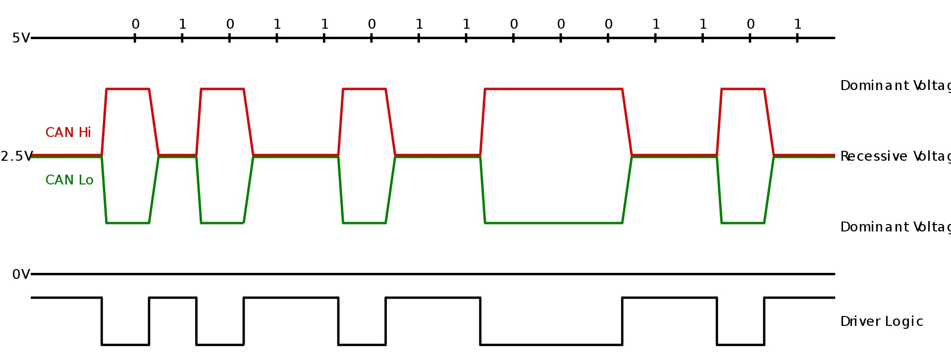
CAN stands for Controller Area Network. It’s a communication protocol that was developed by Bosch in the 1980’s for use in vehicles, and is specifically tailored for communication over long cable runs (up to 40 meters at 1 Mbit/s). It uses differential wiring, and is built around “nodes”. CAN uses the following lines:
CANH: The differential “hi” line CANL: The differential “lo” line
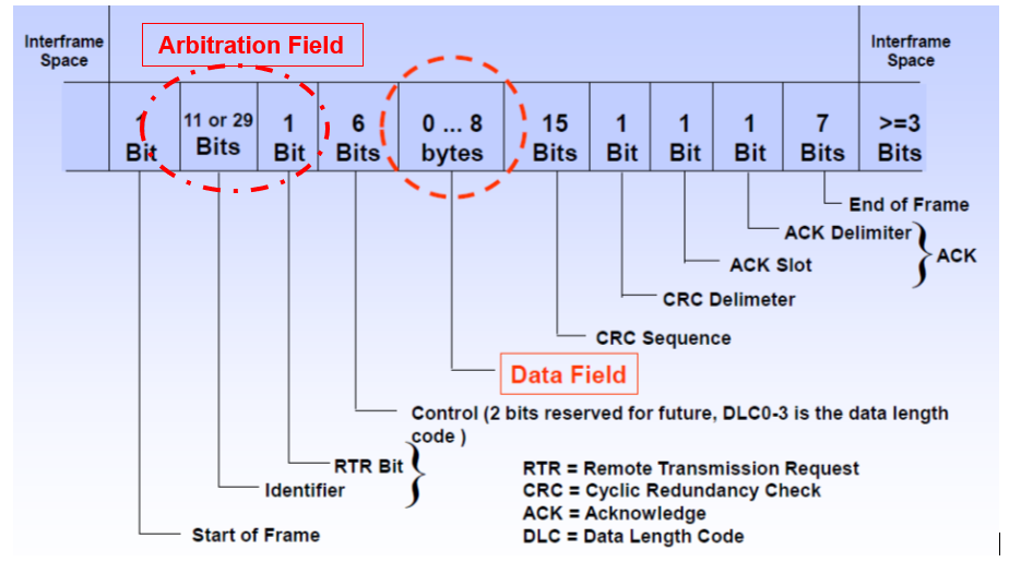
A typical CAN message would look like this:
Each node has an 11-bit ID (29-bit if using the extended-ID protocol). A node begins sending a message by sending its ID. A node configured to receive from that ID will pull the ACK bit low, confirming that it is ready to receive the message. If the ACK bit is not pulled low, the sender will try again a number of times specified by the driver’s configuration. The sender will then send the message, and the receiver will pull the second ACK bit low to acknowledge it received the message. If two nodes send a message at the same time, the lower ID will take priority. A CAN message takes this form:
CAN has many configurations, and is more difficult to get working than the other communication protocols mentioned. It can be useful to first debug in “loopback mode”, in which the lines are internally routed together, such that a device sends and receives to itself. A CAN sniffer (a known-good node) is also an invaluable tool, as behavior on a scope can be misleading as to if messages are actually being sent, or if filter configurations are inaccurate.
A CAN device has TX and RX lines, which are passed to a CAN driver IC to turn these signals into a differential pair. At the end of a CAN line, a termination resistor of value 120 is needed between the CANH and CANL wires. Nodes are meant to be wired in a daisy chain configuration, as opposed to a “star”; a node should be as close to the main line as possible, with pickoffs being kept below 30 cm.