UART stands for Universal Asynchronous Receiver-Transmitter. It’s the communication protocol that makes USB work, and is useful for transmitting larger amounts of data than I2C or SPI. An important detail is the “asynchronous” part - it means that no clock signal is sent between the devices. Instead, the beginning of a message is falling-edge triggered. UART is non-hierarchical, and just has the following lines:
TX: The pin that a device sends messages on RX: The pin that a device receives messages on
A UART message send would look like this:
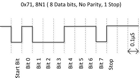 A typical UART message looks like this:
| Start Bit | Data Frame | Parity Bits | Stop Bits |
|---|---|---|---|
| 1 bit | 5-9 bits | 0-1 bit | 1-2 bits |
| UART has fewer configurations than SPI or I2C. The only thing that needs to be matched between communicating devices is baudrate. It’s important to note that the lines between two devices should be crossed; that is, device A’s RX should be connected to device B’s TX: |
UART Wiring
⚠ Switch to EXCALIDRAW VIEW in the MORE OPTIONS menu of this document. ⚠ You can decompress Drawing data with the command palette: ‘Decompress current Excalidraw file’. For more info check in plugin settings under ‘Saving’
Excalidraw Data
Text Elements
Device 1
TX
RX
Device 2
TX
RX
Link to original